

Can You View Registers With Arduino Ide
All the Arduino boards come with a specified number of I/O pins and if there are a big number of devices that are to exist connected with the Arduino board the trouble of shortage of pins might arise. To cater this issue there are shift registers through which nosotros can increase the number of I/O pins of the Arduino. How these shift registers work and how we tin employ them with Arduino, let's find out:
How Shift Registers Work
As described above the shift register is mainly used to resolve the pivot shortage of microcontroller in case when a large number of devices are to be interfaced with the microcontroller. The shift register shifts the data from one bit to some other with respect to the pulses of the clock of the register and the information it shifts is stored in information technology. At that place are three master pins of the shift register: i is the clock pivot , second is latch pin and tertiary is the data pivot.
The pin configuration of a unmarried shift register (74HC595) is given below in the table:
| Pins category (From Left side of grove) | Pin Numbers | Representation | Description |
|---|---|---|---|
| Output pins | one-seven and fifteen | Q1 to Q7, Q0 | Pins at which the device is to be interfaced with controller |
| Power pins | 8 and xvi | GND, VCC | Pins which will power upwards the shift register |
| Serial input | 14 | (DS)SERIN | Pin which receives the information from the controller through serial communication |
| Output Enable | 13 | OE | This pin is LOW when voltage is High and vice versa |
| Latch pin | 12 | (ST_CP)RCLK | When this pin is HIGH the data is sent to the output pins and is also stored in the memory |
| clock pin | 11 | (SH_CP) | Clock pin for the shift register |
| RESET pin | 10 | (SH_CP)SRCLR | Pin use to reset the register past giving information technology LOW state |
| Interfacing of other registers | nine | Q7s (QH') | When more than one registers are to be used, this pivot is used |

Using shift register with Arduino
To explain how we can use the shift annals with Arduino nosotros have demonstrated an example of connecting multiple LEDs with Arduino Uno through a shift register. Here is the list of components that nosotros have used in this example:
- Breadboard
- Connecting wires
- viii LEDs
- Arduino Uno
- 74HC595 Shift Register
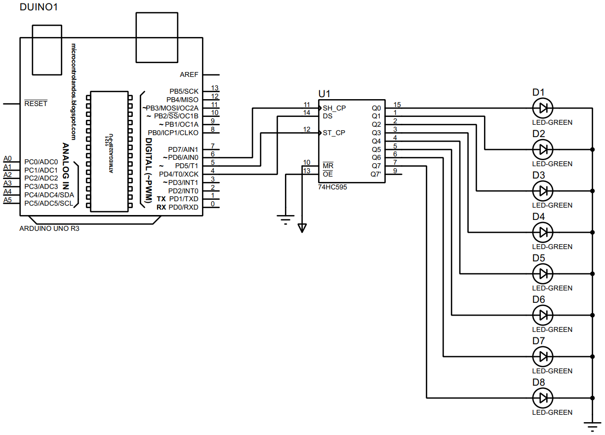
Nosotros have designed the excursion using the above listed components and its schematic is given below:
Hardware assembly for using shift register with Arduino Uno
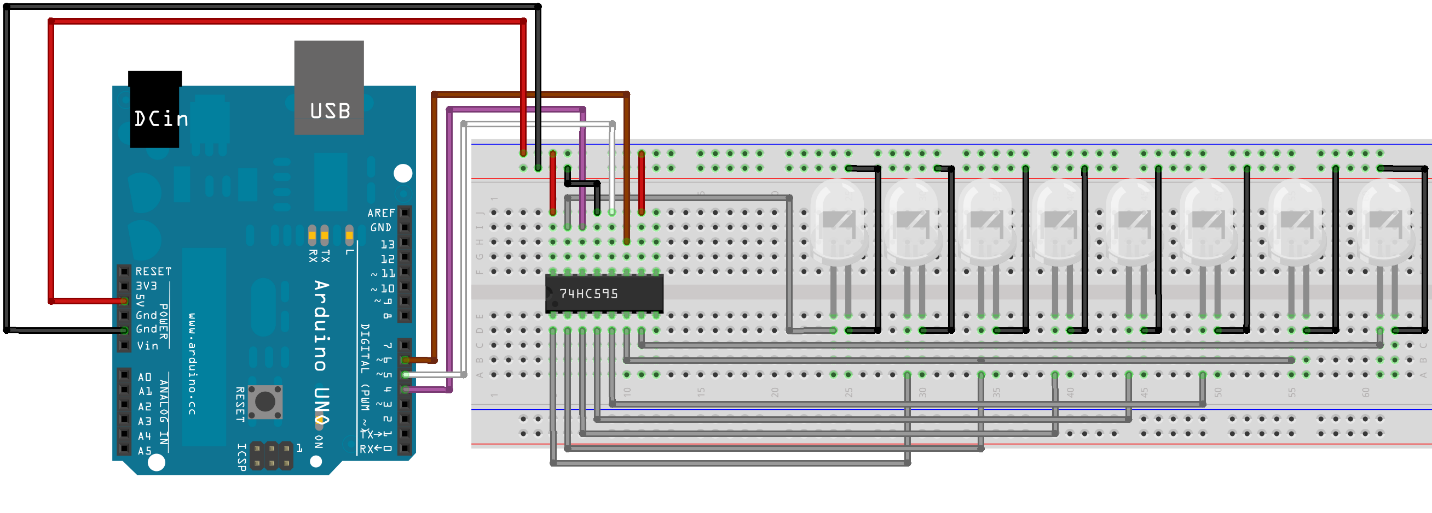
To run across how the circuit volition look similar on the breadboard we have kickoff fabricated the hardware associates every bit in the epitome beneath:
For your understanding we take explained the connections of the components used in the circuits:
- The regal wire shows the information pin connexion of the shift register with Arduino using its pivot 4.
- The white wire represents the connexion for the latch pin with Arduino Uno that is connected to its pin 5 whereas the brown wire is used to connect the clock of the shift register with Arduino using its pin half-dozen.
- To connect the LEDs with the shift register we have used the gray wires and the grounding of the LEDs is done by using the black wires.
- For connecting the shift register with supply we have used the five-volt option of the Arduino from its power supply pins.
Arduino code for using shift register with Arduino Uno
To use shift register with Arduino we have to configure it by programming the microcontroller so below we accept provided the code:
int latch = v ; // pins 5 of Arduino for Latch pivot of shift register
int clock = 6 ; // pins half-dozen of Arduino for clock pin of shift register
int data = 4 ; // pins 4 of Arduino for information pin of shift register
byte led = 0 ; // Variable which will save the value of LEDs
void setup( )
{
// assigning the working modes to the pins of shift register
pinMode(latch, OUTPUT) ;
pinMode(data, OUTPUT) ;
pinMode( clock , OUTPUT) ;
}
void loop( )
{
led = 0 ; // at the first all the LEDs volition remain in off state
ShiftRegister( ) ; // turn on the adjacent LED
filibuster( 500 ) ;
for ( int i = 0 ; i < 8 ; i++ ) // loop that will turn the LED 1 past i
{
bitSet(led, i) ; // assigning the respective LED the HIGH values
ShiftRegister( ) ; // plow off the previous LED
filibuster( 500 ) ;
}
}
// role that will update the annals after each iteration of for loop
void ShiftRegister( )
{
digitalWrite(latch, Depression) ;
shiftOut(data, clock , LSBFIRST, led) ;
digitalWrite(latch, Loftier) ;
}
Hardware Demonstration
We have implemented the circuit designed for interfacing the 74HC595 shift register with Arduino Uno according to the hardware assembly that we have described earlier. To demonstrate how we accept plough the LEDs in a pattern we accept given the animated Gif beneath:
Conclusion
Shift registers are used generally when we have to increase the I/O pins of the microcontrollers so that we tin can interface more devices with information technology. To demonstrate how we can use the shift register nosotros interface 8 LEDs with the Arduino microcontroller by only using its 3 pins. For further clarification we have given circuit schematic and its implementation of hardware forth with the Arduino sketch used to program the controller.
About the author
![]()
I am an electrical engineer and a technical blogger. My slap-up involvement in embedded systems has led me to write and share my cognition most them.

Can You View Registers With Arduino Ide,
Source: https://linuxhint.com/shift-register-arduino/
Posted by: estradainving.blogspot.com
0 Response to "Can You View Registers With Arduino Ide"
Post a Comment